Analog Pocket Connector
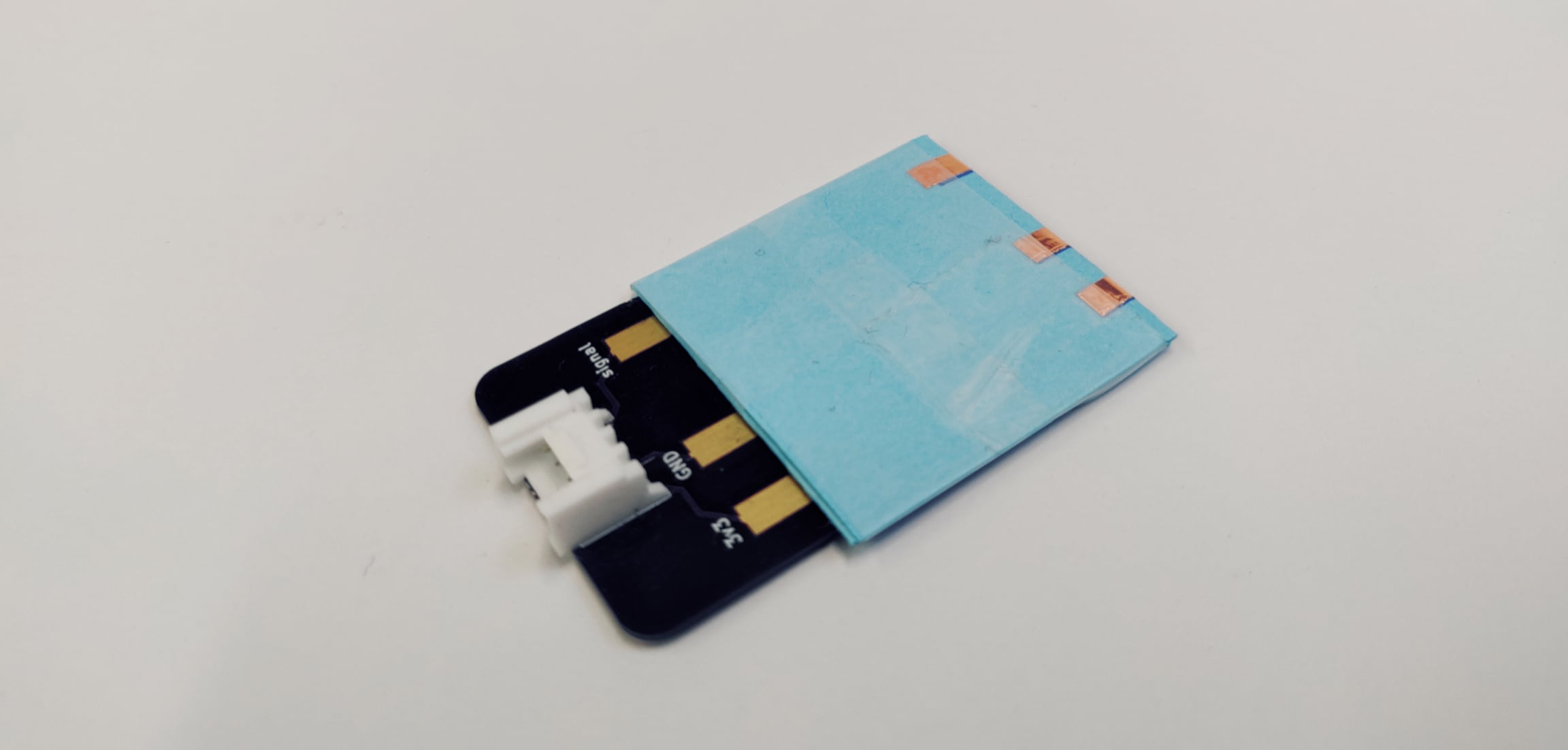
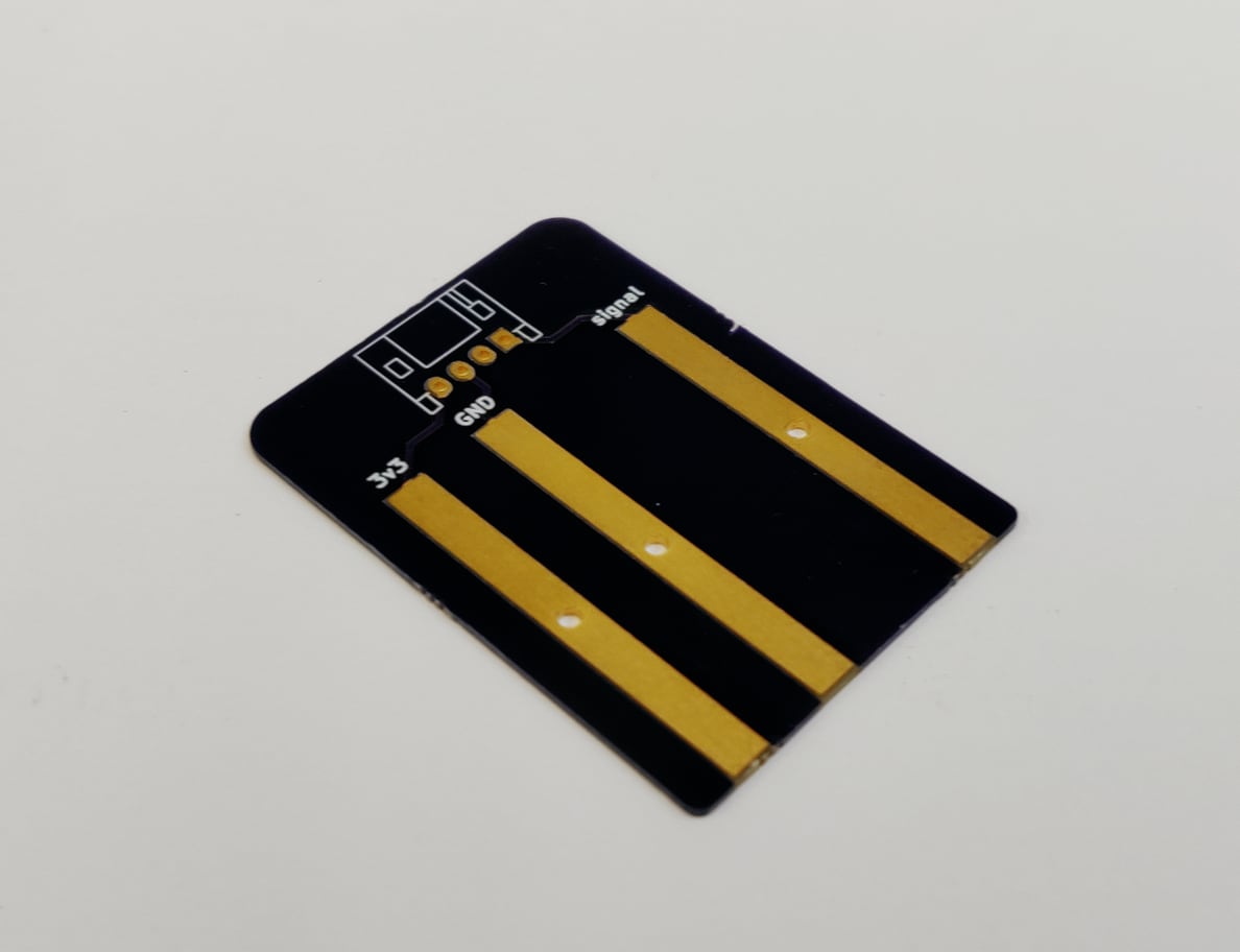
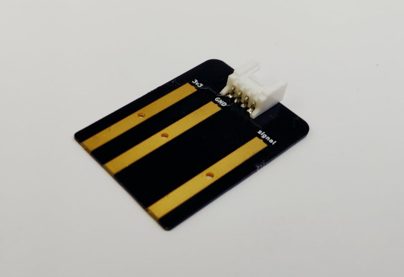
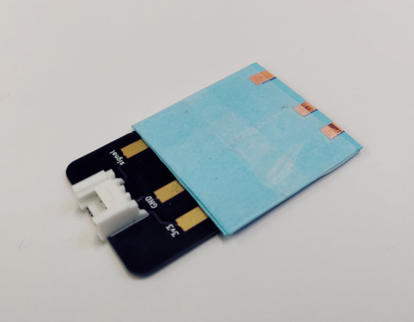
The Analog Pocket Connector connects analog sensor circuits to the Paper Capelet. It breaks out the 3.3V, GND, and analog pin connections on the Grove connector. These are electrically connected to a folded paper pocket that then provides a mechanical and electrical connection to the sensing circuit.
You need to order or fabricate the printed circuit board (PCB), and then can add the rest of the components.

Building the Analog Pocket Connector
You will need
Analog Pocket Connector PCB
Paper template
Strip of 0.25”/5mm copper tape
Scotch/Sello tape
Soldering equipment
Steps
Order directly or download the gbr files from OSH Park and fabricate the PCB.
Solder the Grove connector to the PCB, following the outline of the silkscreen.
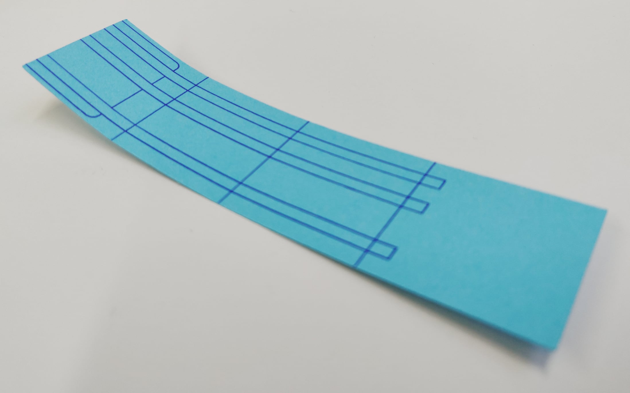
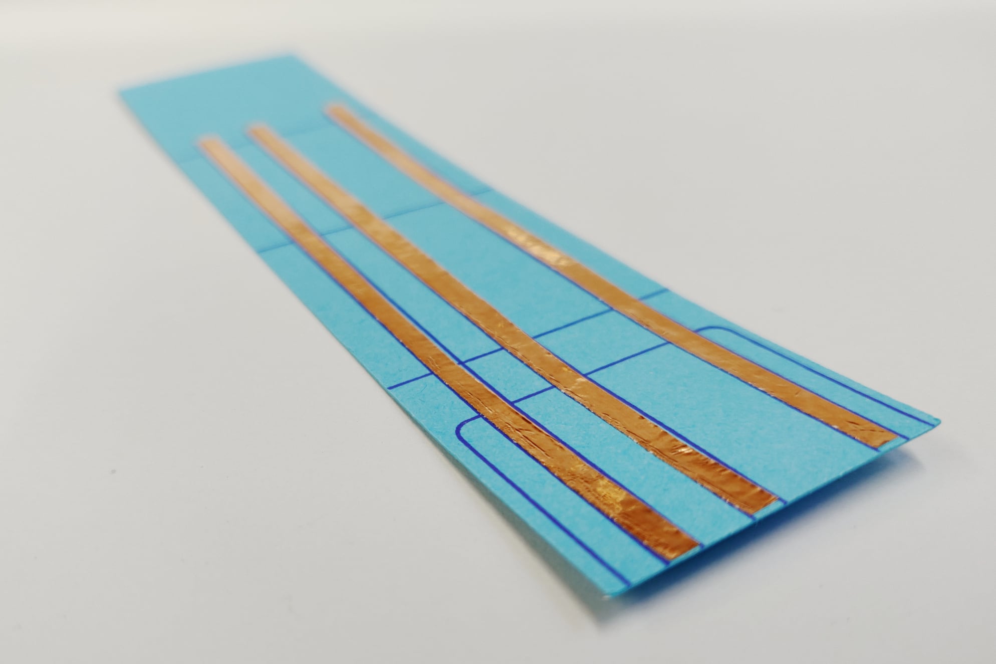
Download the template from the embelashed repository. The .studio3 file is for a Silhouette machine and the other files can be used with a printer or laser cutter. The red lines are where the template should be cut and the blue lines are where an outline should be drawn.
Cut out the paper template using your preferred method.
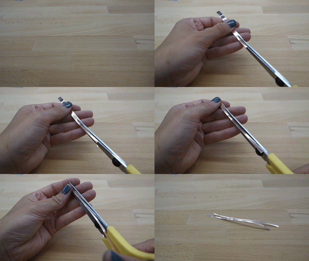
Cut the copper tape in half lengthwise with a pair of scissors.
Stick the three pieces of copper tape onto the paper template, following the outlines.
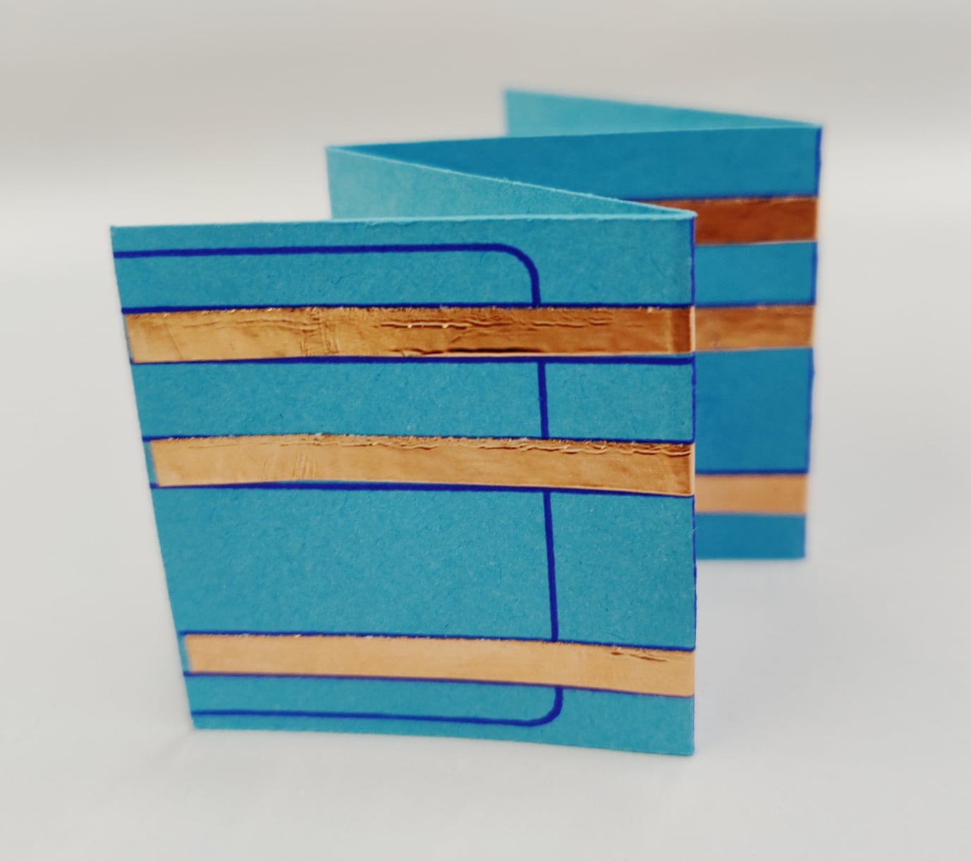
Fold the template along the guidelines. Start by folding the template in half with the copper tape on the inside. Then fold along the other two lines to create an accordion shape.
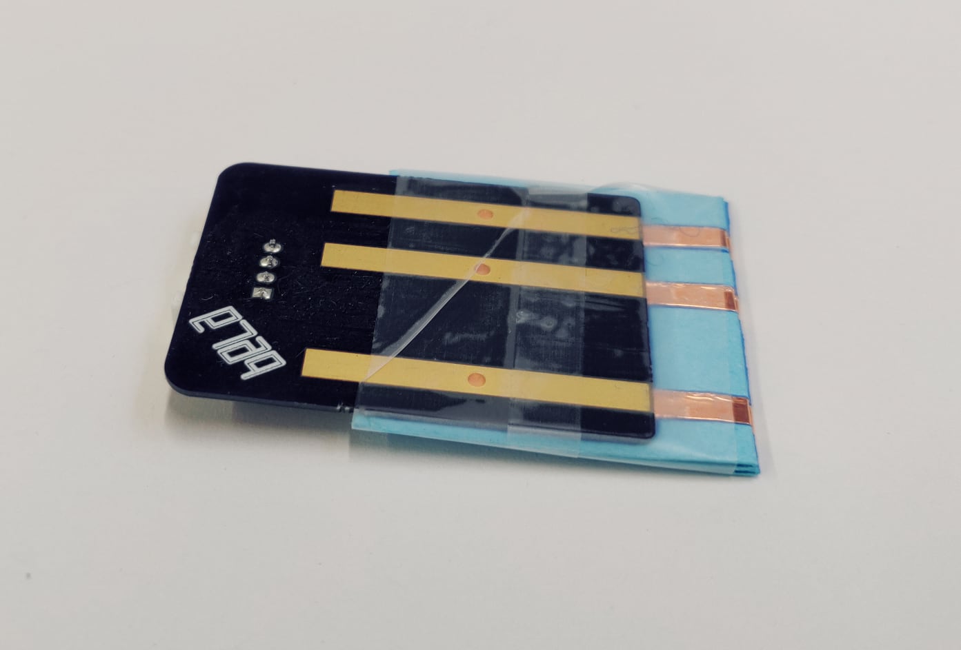
Identify the side of the folded template with an outline that matches the edge of the PCB. It is also the side with more copper tape. Place that side on the top of the PCB, lining up the outline with the edge of the PCB.
Using non-conductive tape like scotch/sello tape, tape the paper template to the PCB, taking care to leave open the pocket edge.
Warning
embelashed uses Grove connectors to connect Pocket Connectors to the Paper Capelet, but be aware that the Analog and Digital Pocket Connectors do not follow the standard pin arrangement found in other Grove sensors.
